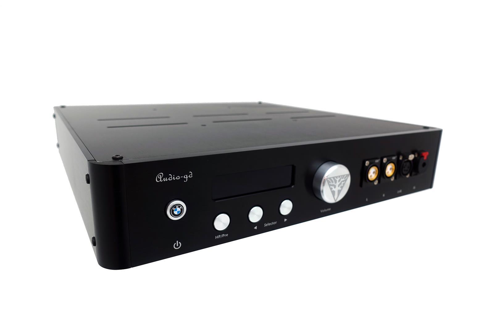
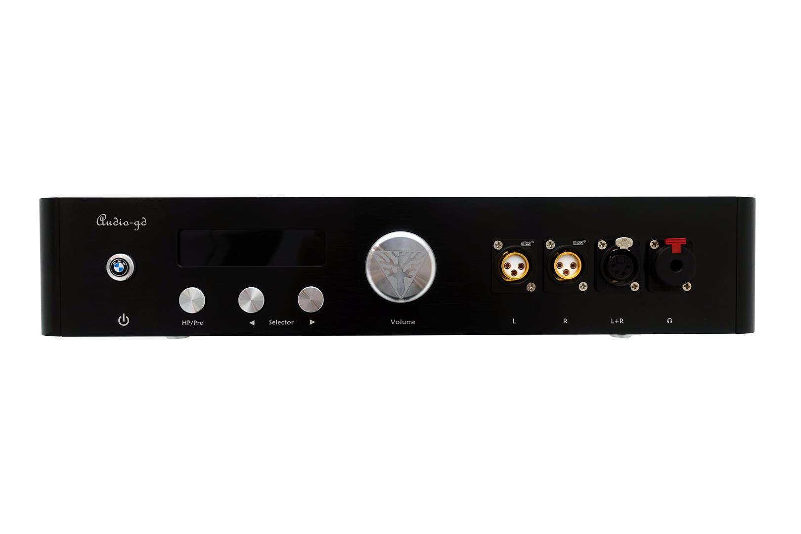
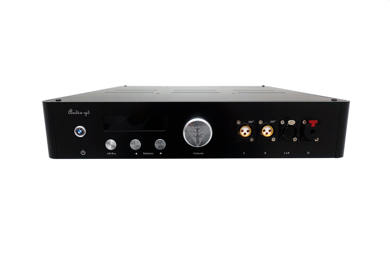
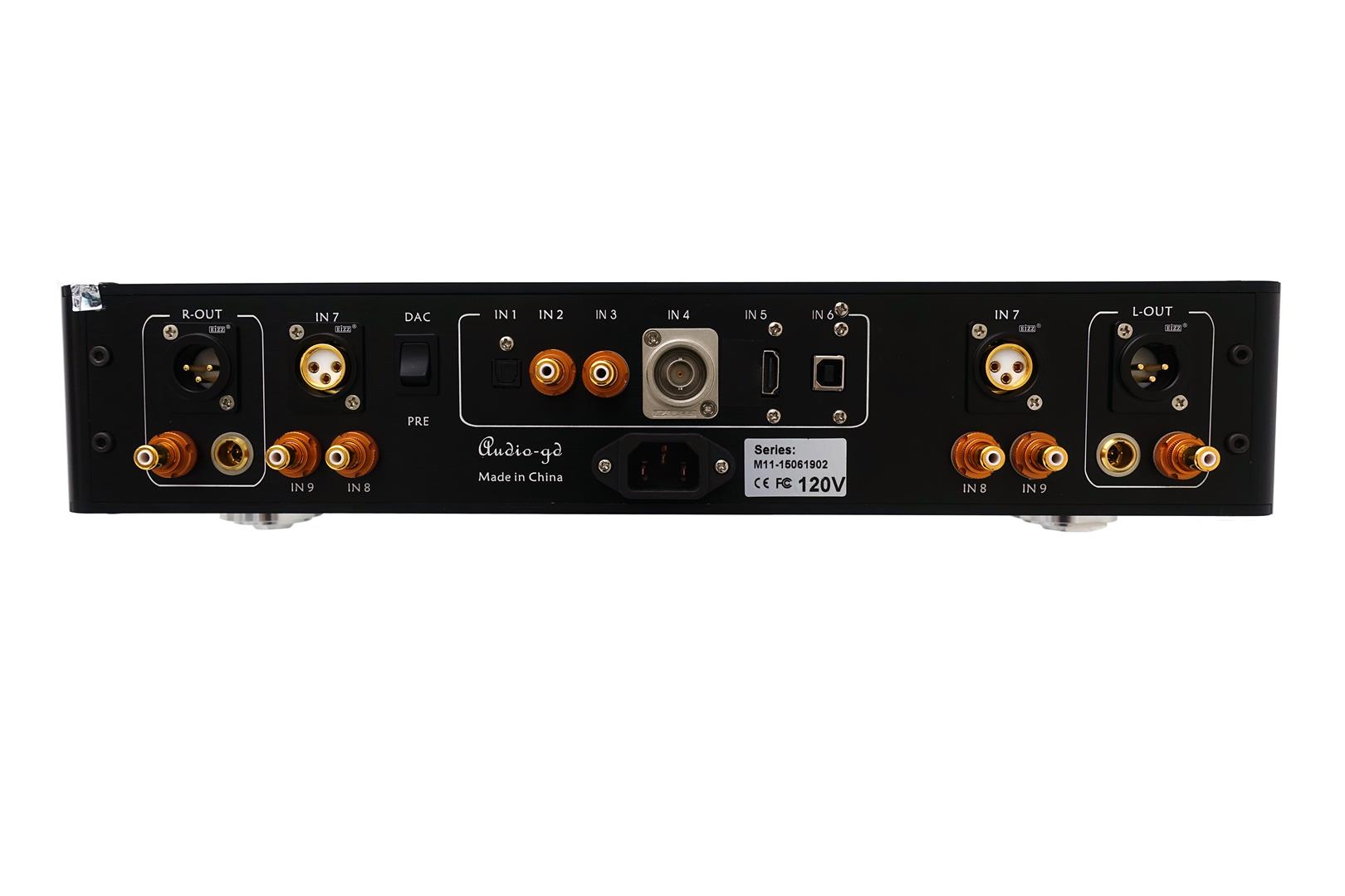
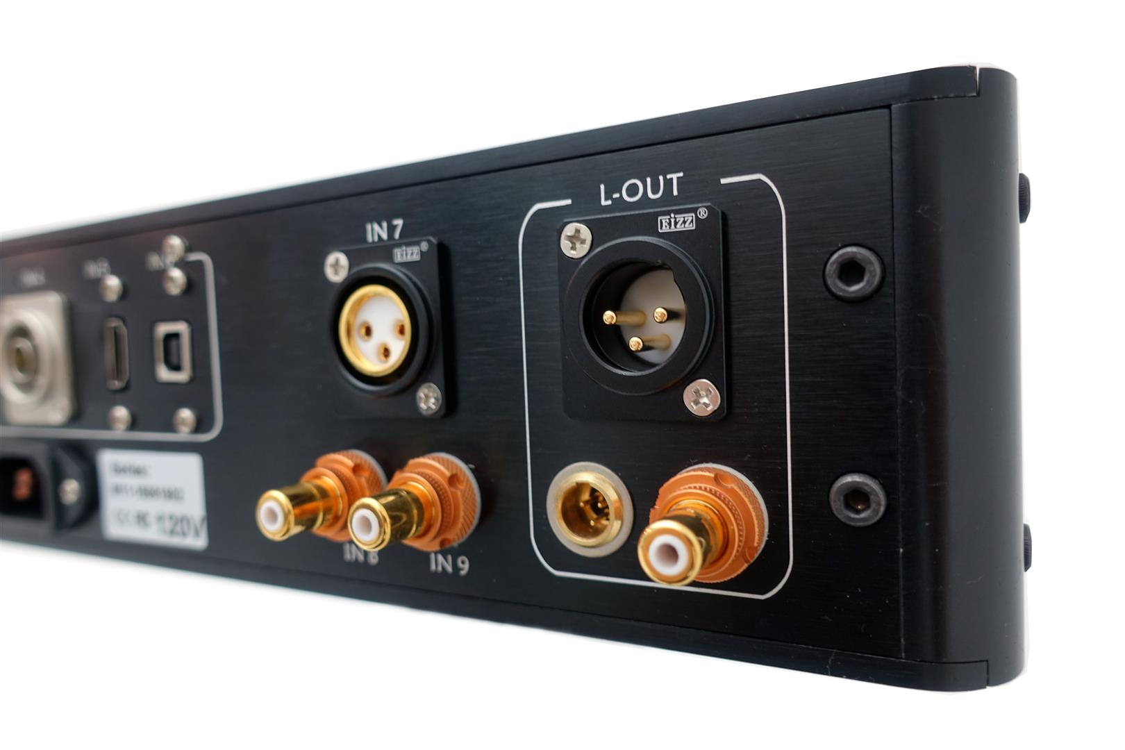
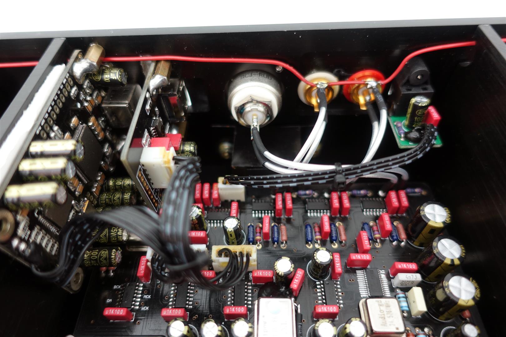
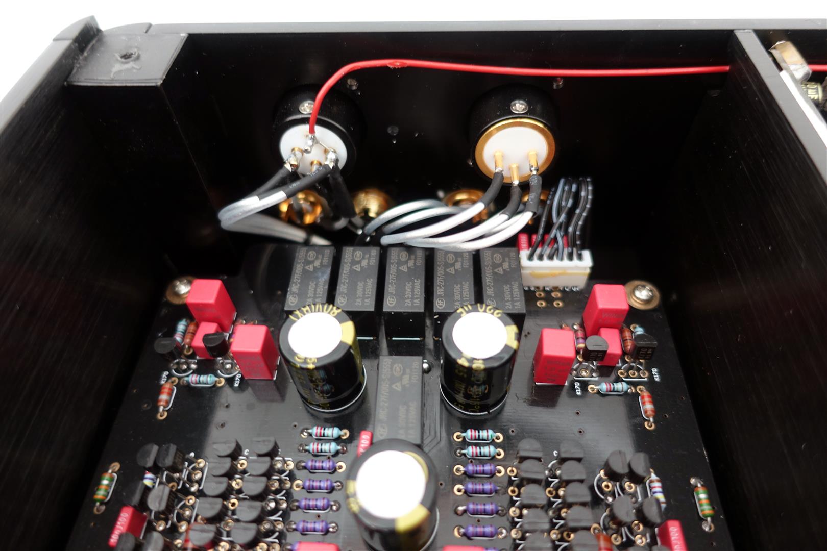
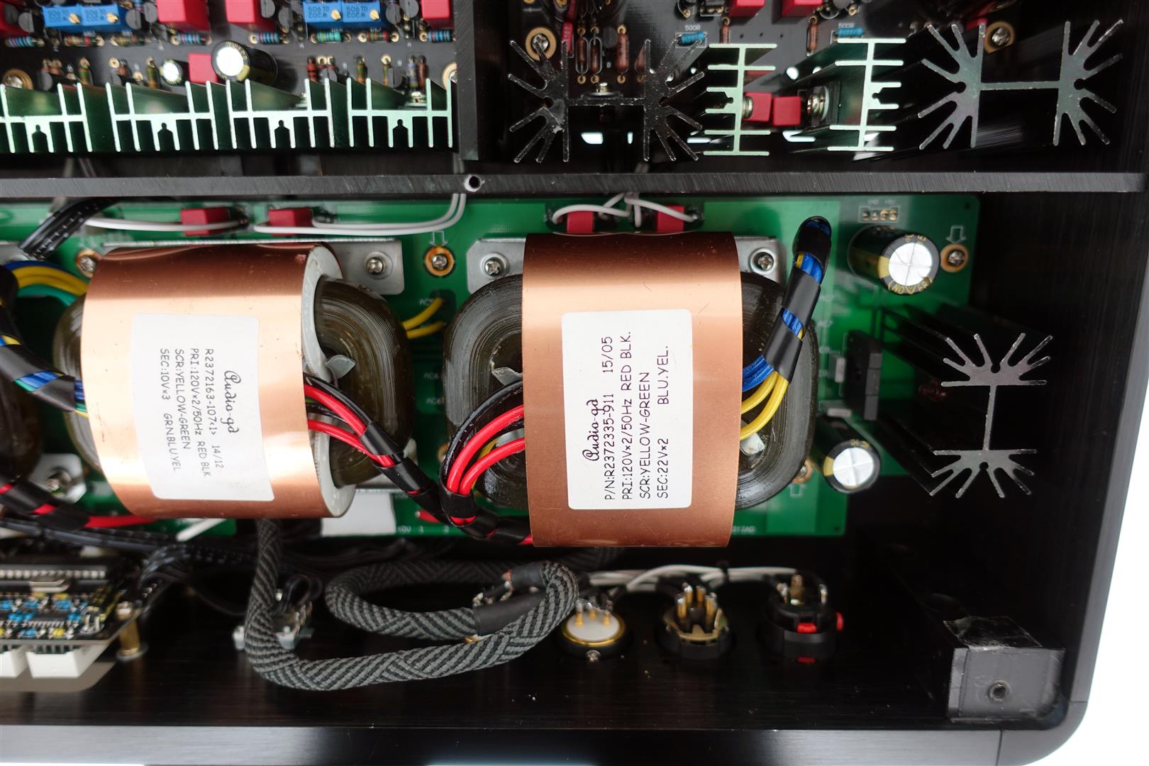
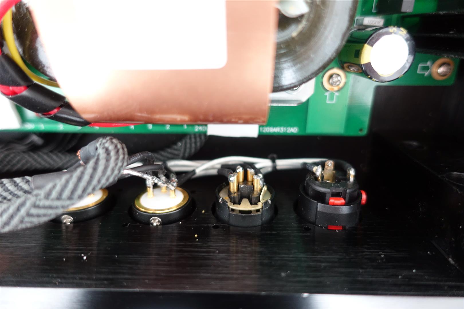
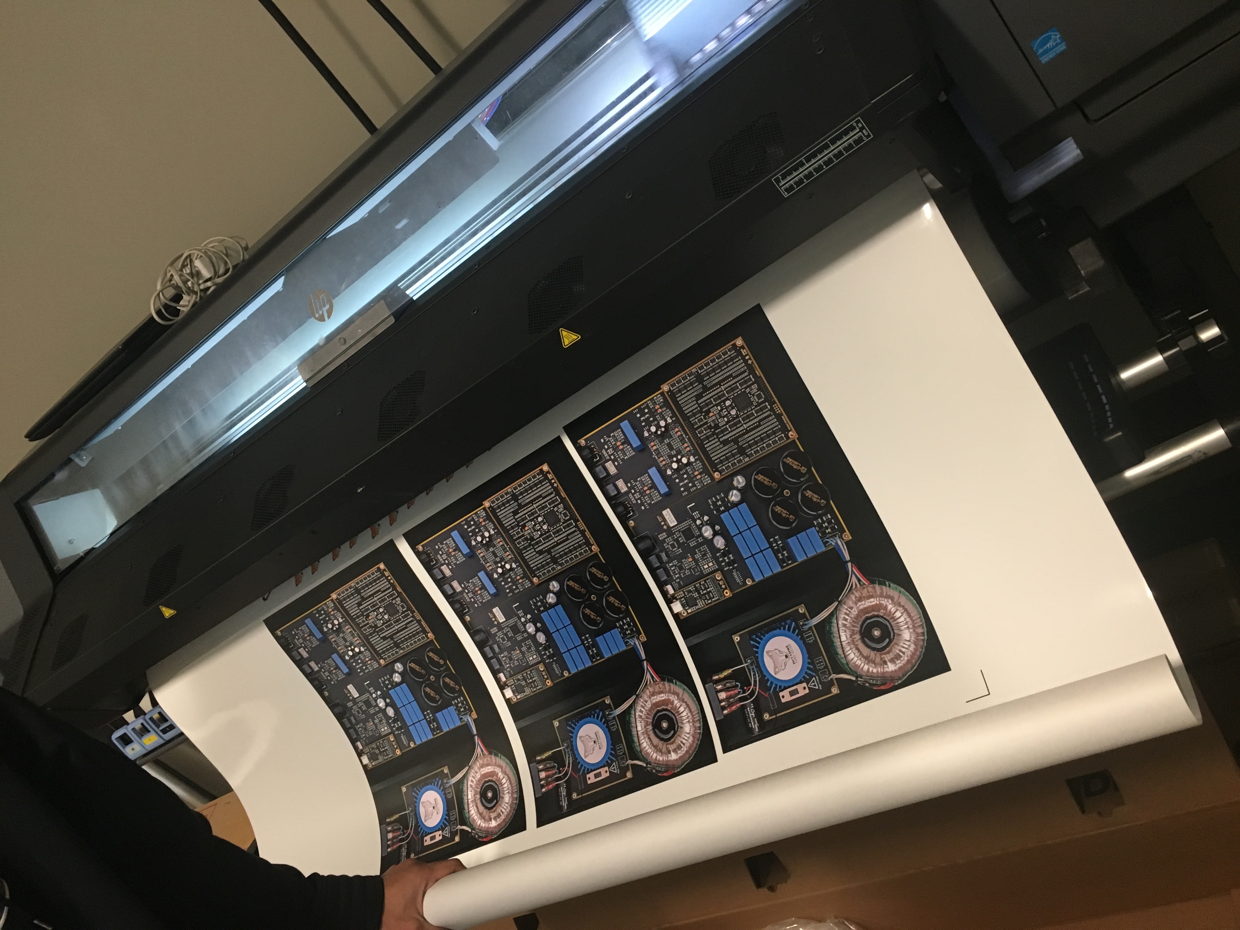
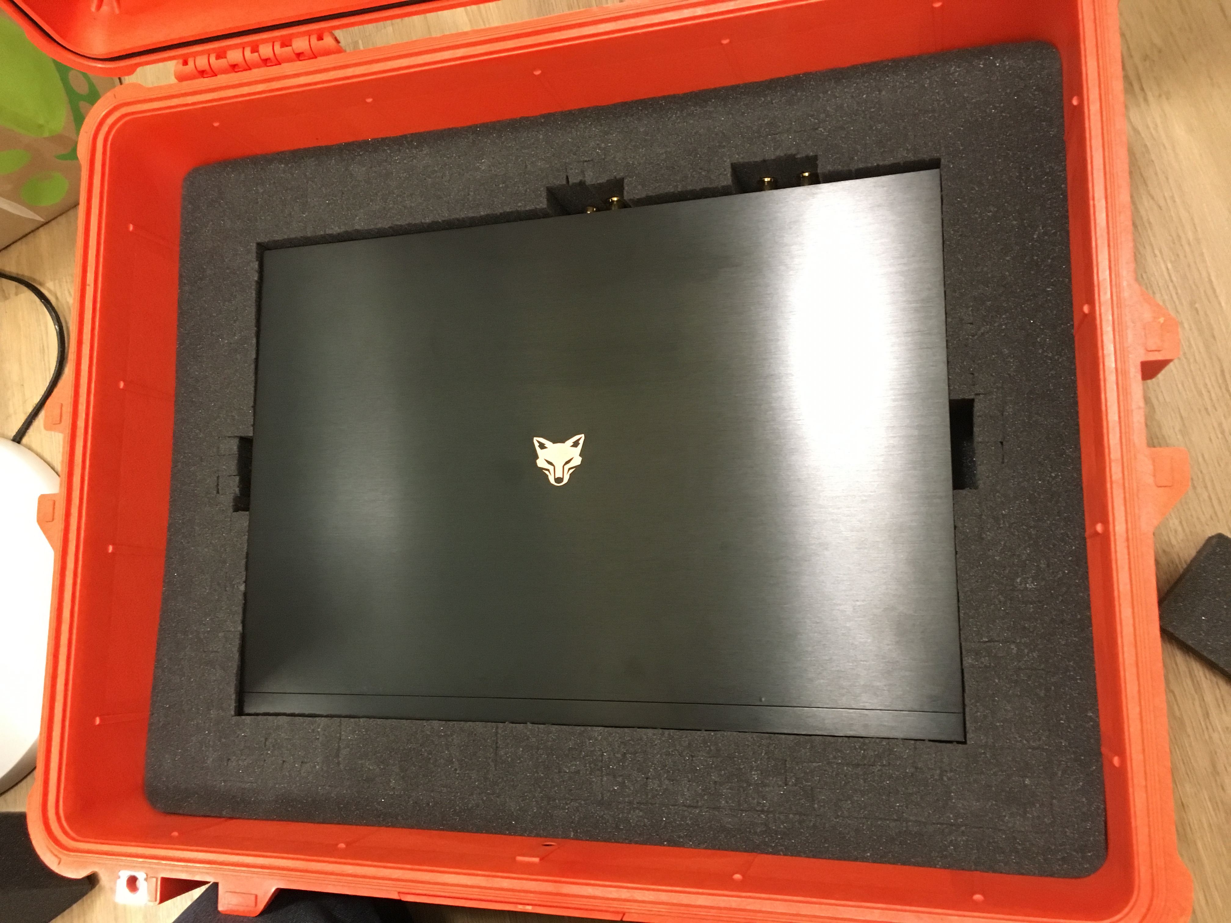
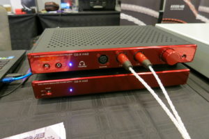
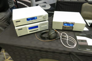
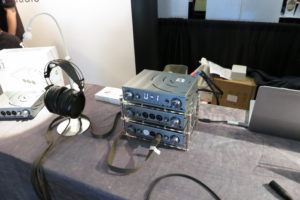
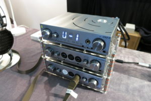
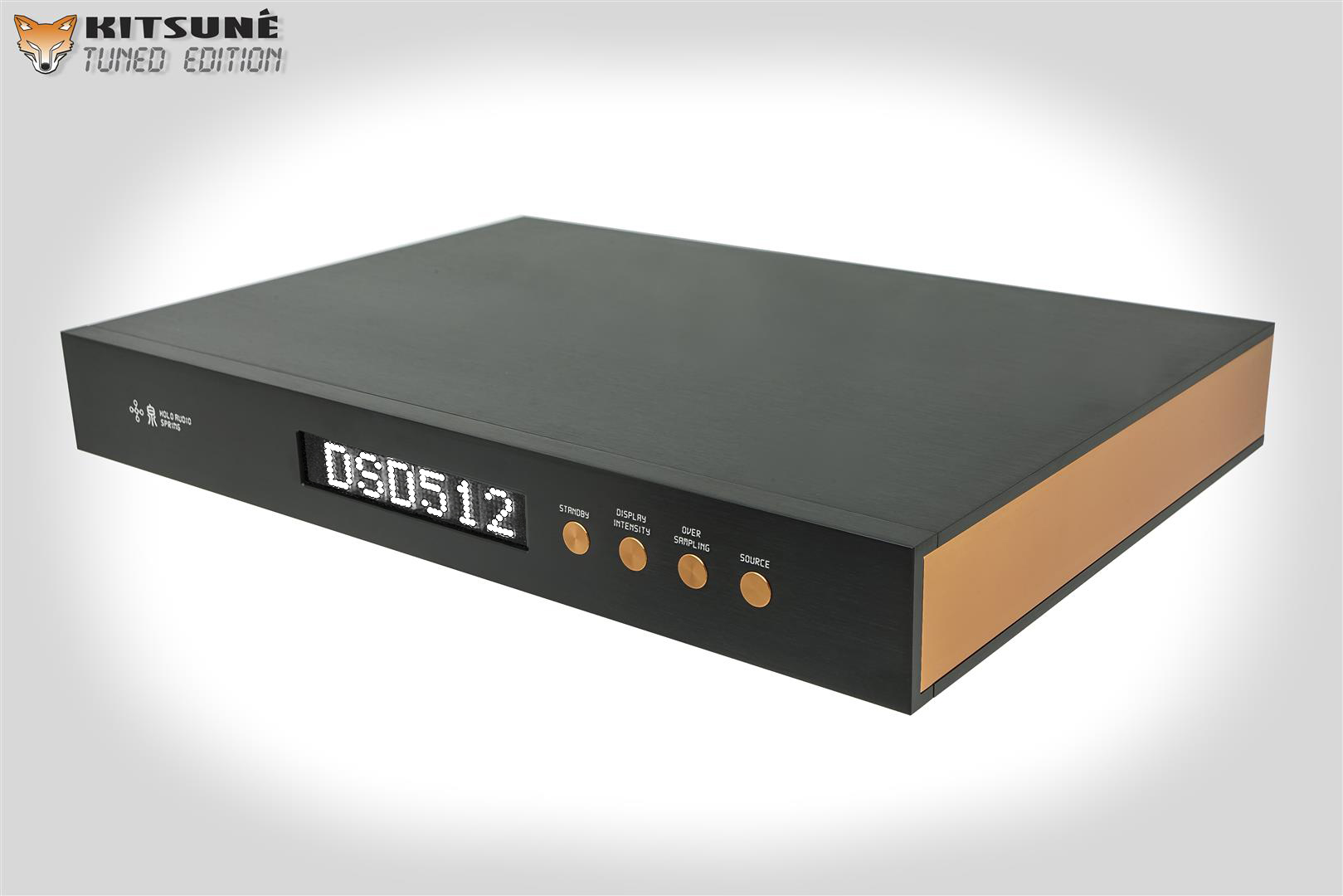
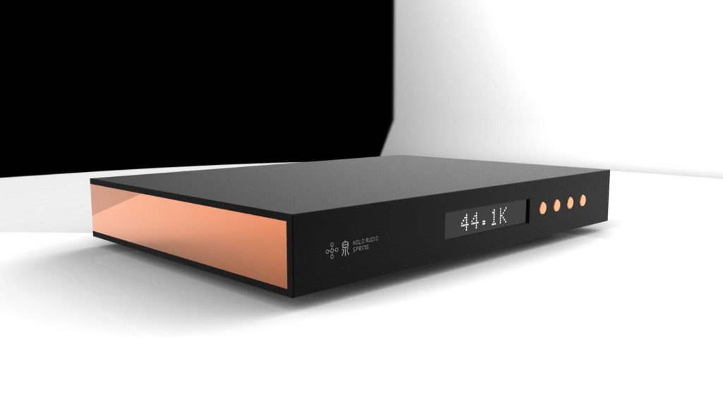
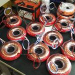
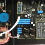
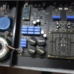
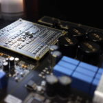
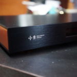
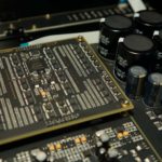
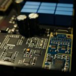
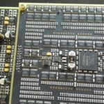
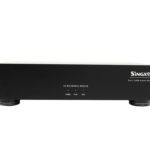
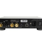
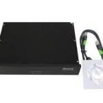
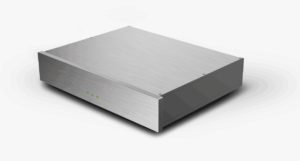
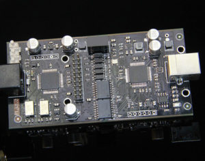
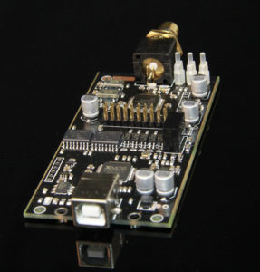
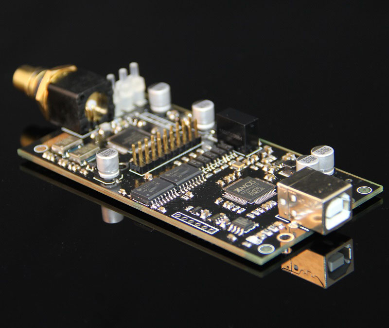
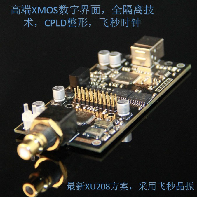
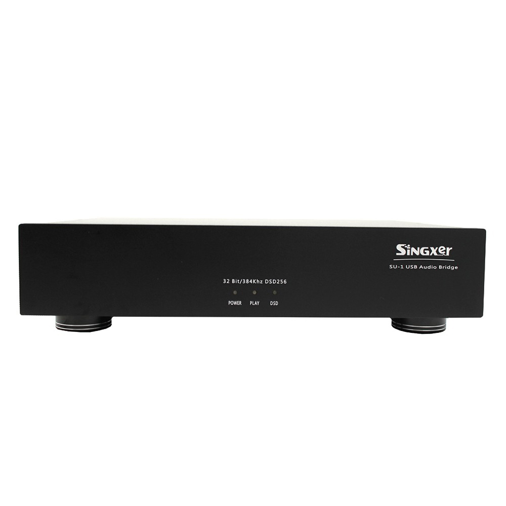
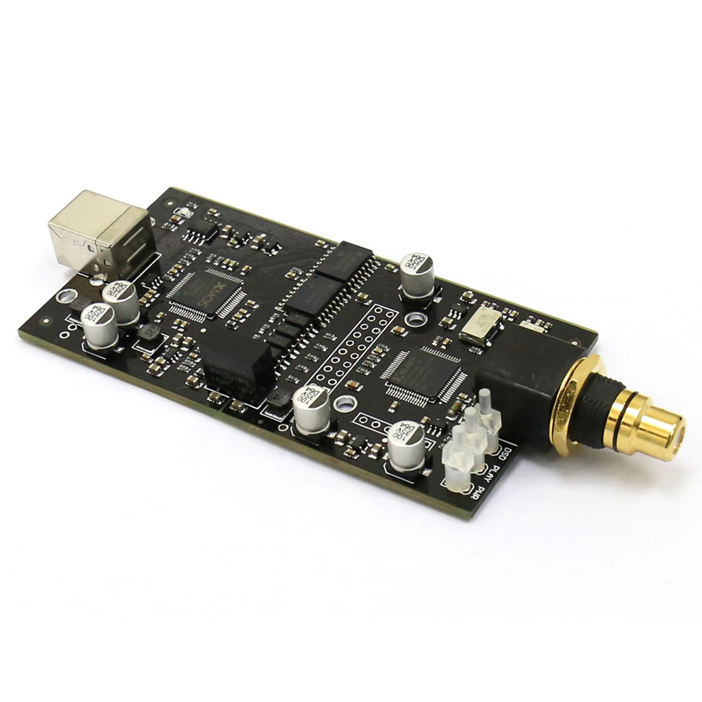
SU-1 digital interface is Singxer team developed a high-performance USB digital audio interface, using the latest XMOS family and Xilinx high-performance CPLD / FPGA chip. SU-1 is the rare use femtosecond system clock digital interface, Crystek of two CCHD-957 SU-1 crystal is the ultimate output audio signal quality has laid a solid foundation. SU-1 digital input interface using a standard USB2.0 interface. SU-1 has a wealth of output interfaces, including coaxial RCA and BNC output S / PDIF, XLR balanced outputs AES / EBU, HDMI output IIS (including DSD ON and MUTE signals) and BNC WCLK word clock output.
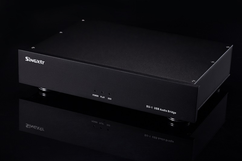
SU-1 is the first machine we have developed equipment that is positioned in the high-end interface, is used mainly in the following three main technologies:
1, full isolation technology (ground isolation), the use of 150Mbps full-chip isolation, interference can be completely isolated from the PC;
2, source synchronous shaping technology and CPLD technology, I2S signal isolation after the re-shaping; thus eliminating the isolation chip to bring added jitter;
3, the independent development of the system clock, using CRYSTEK high-performance oscillator, low phase noise and low jitter.
Features:
1, SU-1 is the first using the XMOS latest xCORE-200 series of high-end USB digital interface products. New generation XMOS chip, using more advanced process technology, performance than the older U8 chip doubled, reaching 1000MIPS processing capabilities.
2 , it is known, the weight of the core is digital audio algorithms. Our team in the field of digital audio work for many years, at the same time get XMOS FAE support team, we conducted a number of technical improvements and optimization algorithms on the basis of the original firmware.
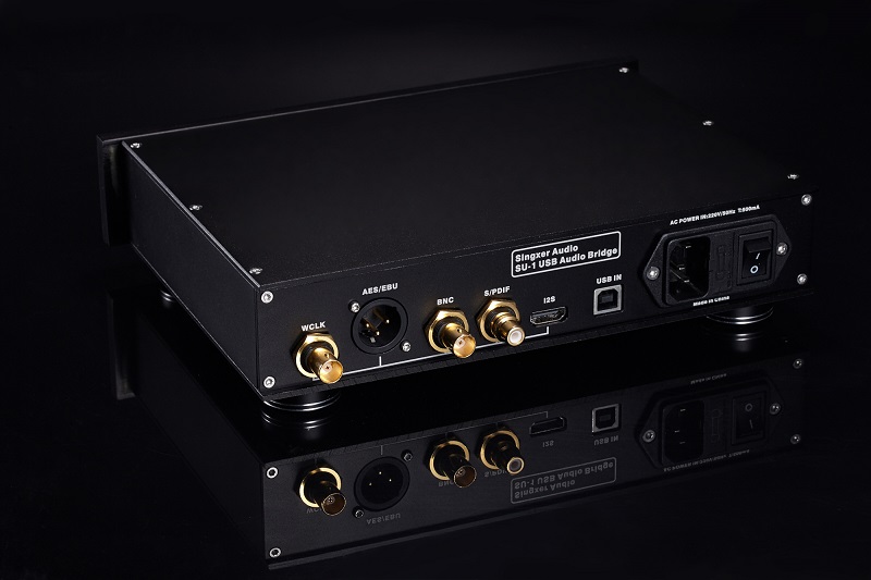
Specifications:
Each output interface supports sample rates:
PCM: 44.1KHz,48KHz,88.2KHz,96KHz,
176.4kHz, 192KHz, 352.8KHz, 384kHz
[ Wherein I2S out support full sample rate , S / PDIF supports up to 192KHz]
DSD: 2.8 MHz (DSD64) – DoP,native
5.6 MHz (DSD128) – DoP,native
11.2 MHz (DSD256) – DoP,native
[ Wherein I2S out support all DSD format , S / PDIF and AES / EBU support DSD64 DOP mode ]
位宽:最高32 bit over I2S output
最高24 bit over S/PDIF
Each interface electrical standards:
1 , the USB input socket is a standard USB-B type female, the USB power supply range 4.5V-5.1V ;
2 , the RCA connector outputs standard S / PDIF signal level is 550mV ( access standard load ), the output impedance of 75 ohms;
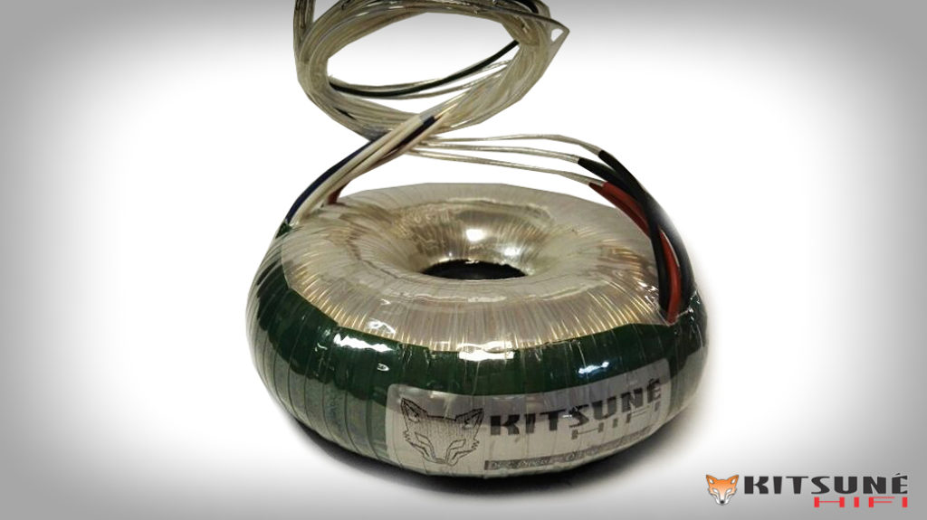
3, the power input is 220V AC, internal use RS importing adapter for power.
Design details:
1 , carry out electricity as the mother of the acoustic design concept, pay attention to the power supply circuit design, high-performance, low noise and fast response of the LDO as the main power source. The entire board using multiple independent path LDO power supply, wherein the clock even partially adopted ADI ‘s ultra low noise LDO , in order to ensure the ultimate output performance laid a solid foundation.
2 , the PCB motherboard with 4 -layer circuit board design, ensure that you have full power and ground plane layer, using the method of high-speed digital design, signal integrity and power integrity of the entire board. The clock signal for special treatment, using package design and precise impedance control, thereby ensuring the signal quality and increase the clock anti-jamming capability. Input and output signals follow a standard design, especially USB high speed signals using a 90 ohm differential impedance control.
System Compatibility:
1, Windows XP, Windows 7, Windows 8; 32/64 bit, you need to install special drivers
2, Native MacOS 10.6 and later, using the system comes with drivers
3, Native Linux with UAC2 compliant kernel, using the system comes with drivers
4, Android OS 4.2 and above, the need to support OTG function.
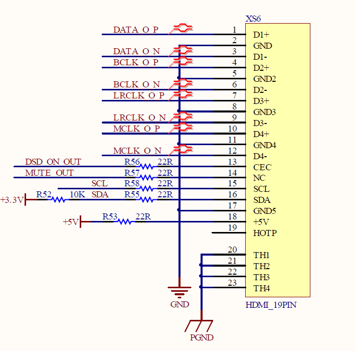
I2S interface with HDMI output socket:
1. The level of 3.3V for the LVDS differential signals;
2. The output signal is muted, DSD ON signal, 5V power supply (low current);
3. The output signal mute, DSD ON signal can be modified according to customer needs, internal CPLD can define different output pins; the two signals can be output to any socket PIN13,14,15,16 pins.
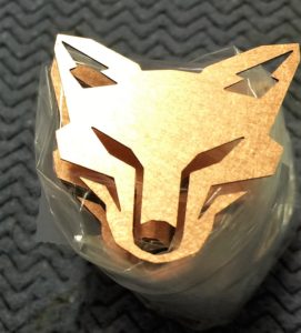
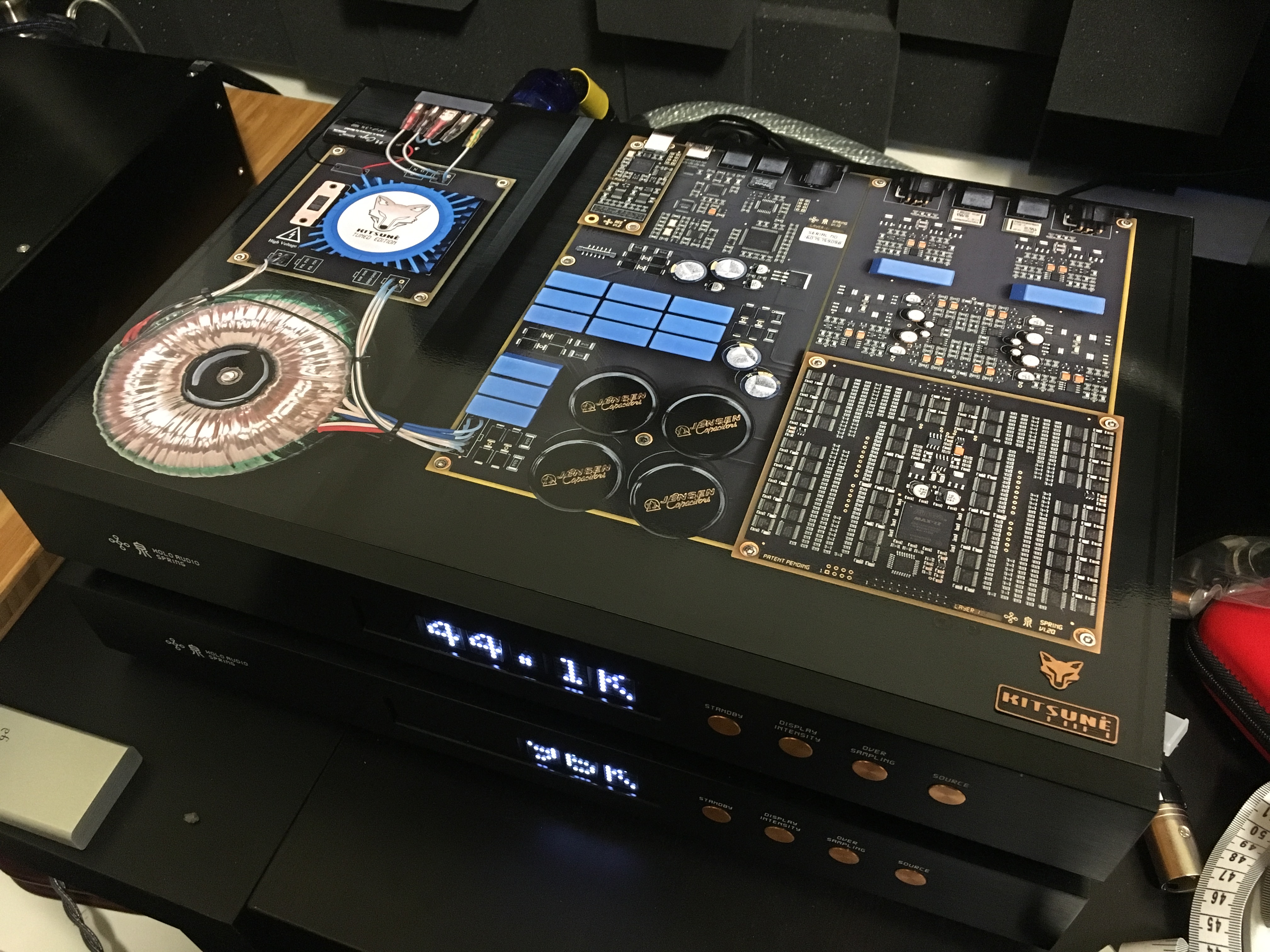
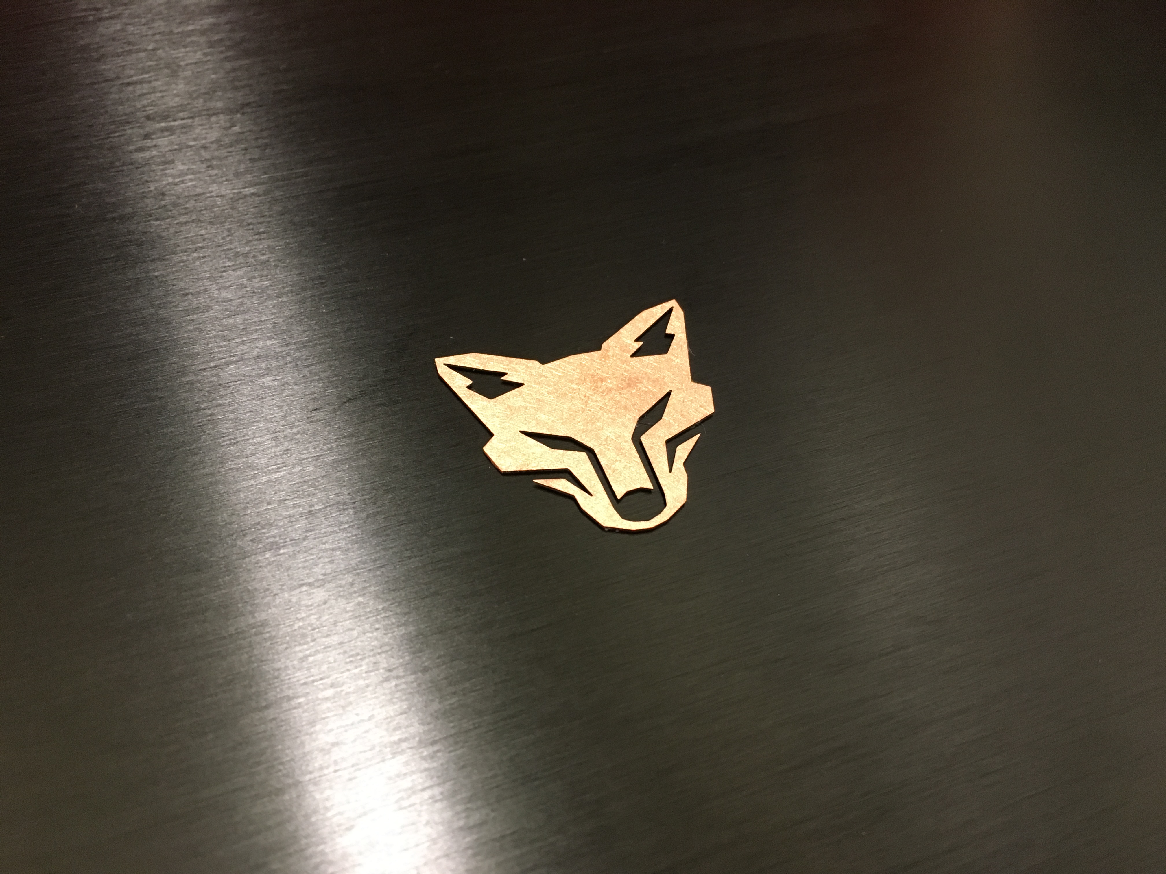
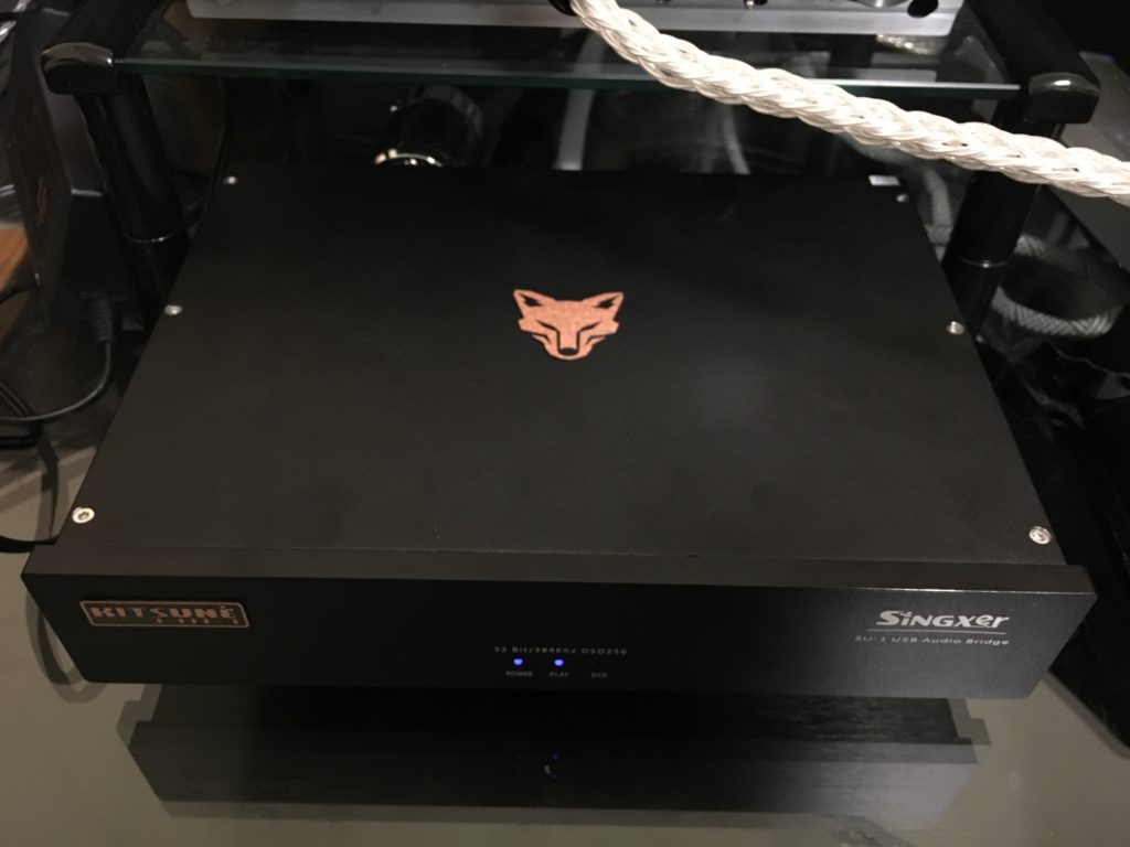 Solid copper KitsuneHiFi fox badging is available for KTE products (we sell these to customers who would like them for their official KTE dac)
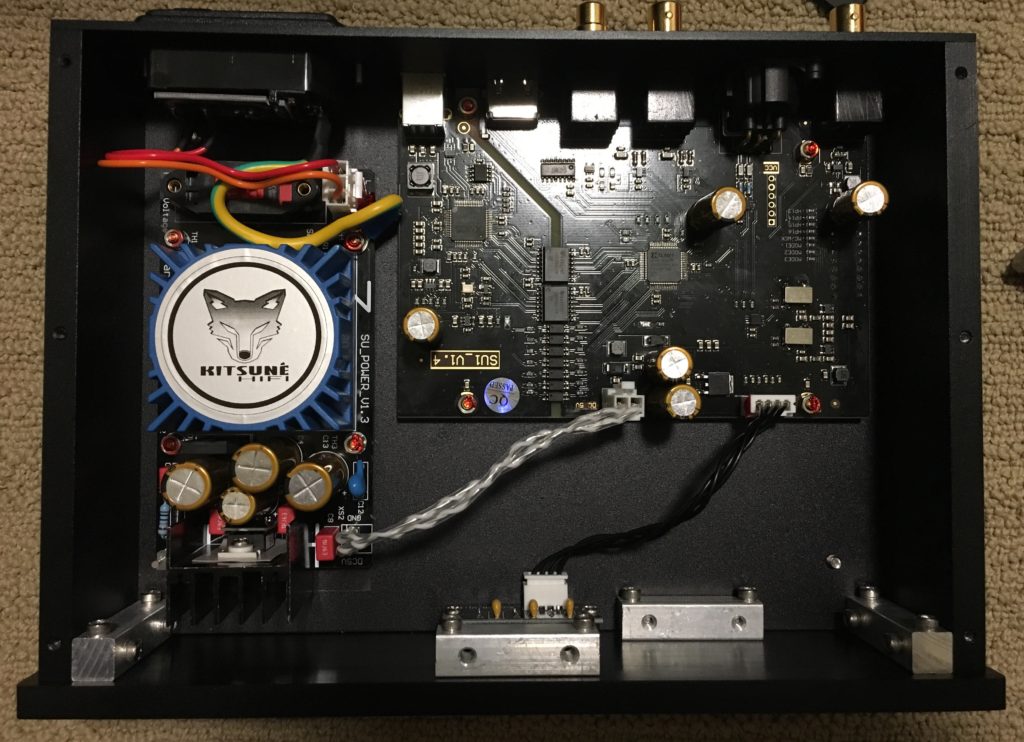
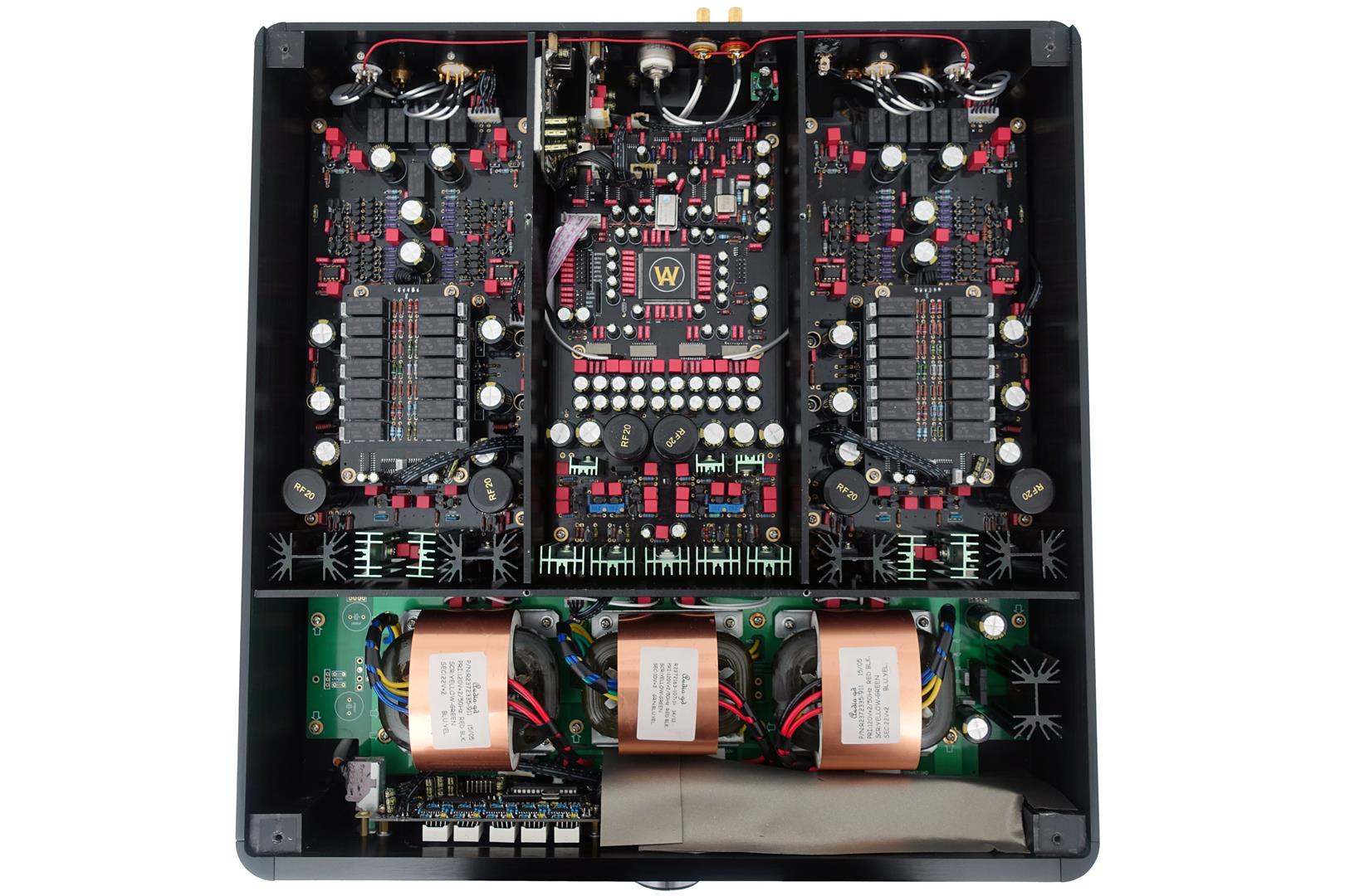
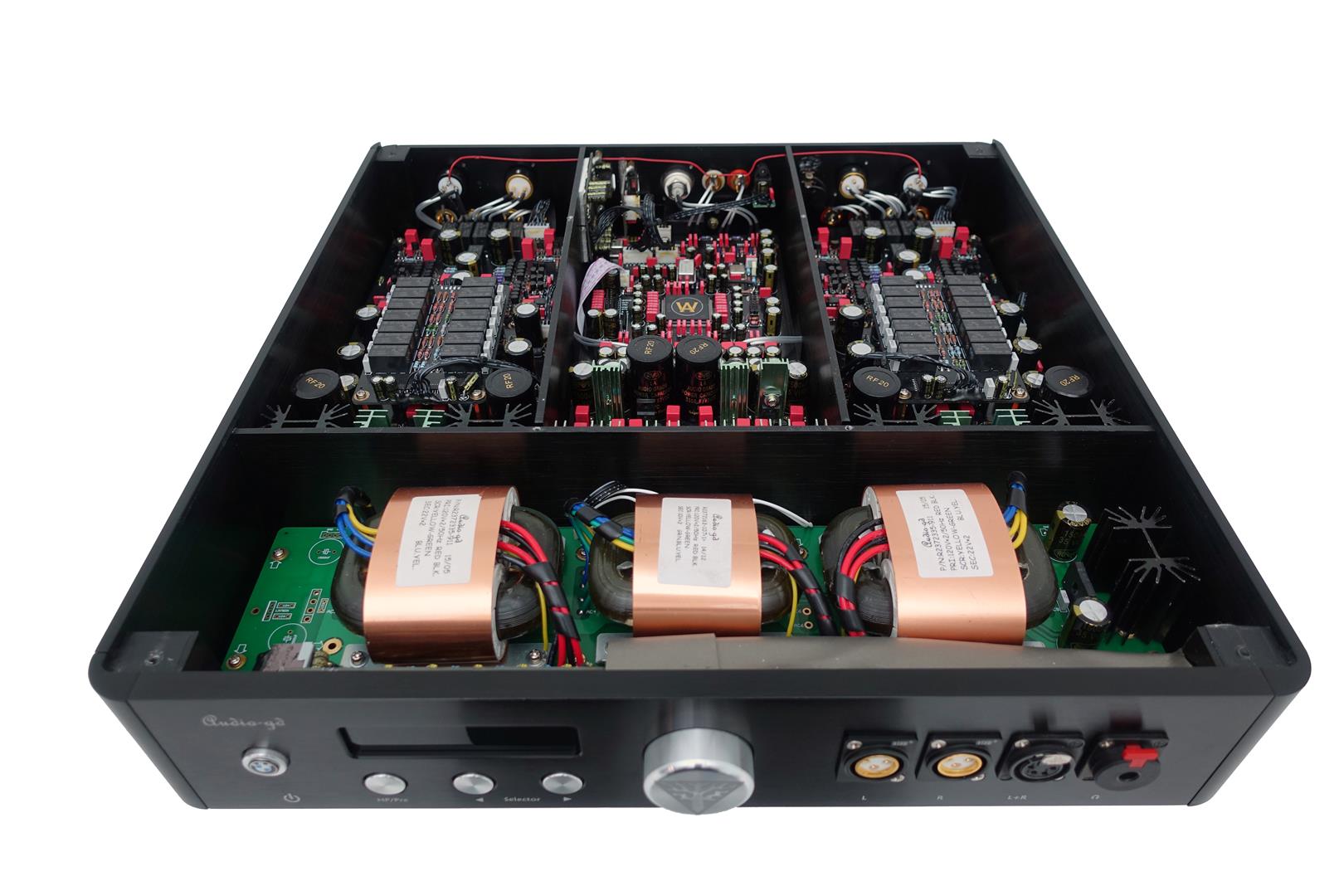
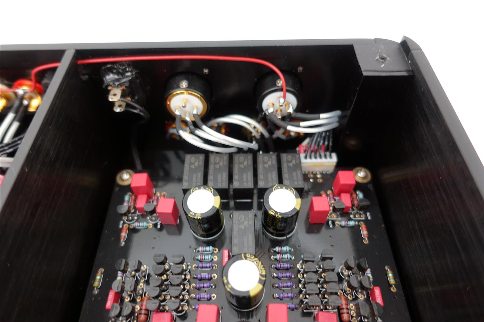
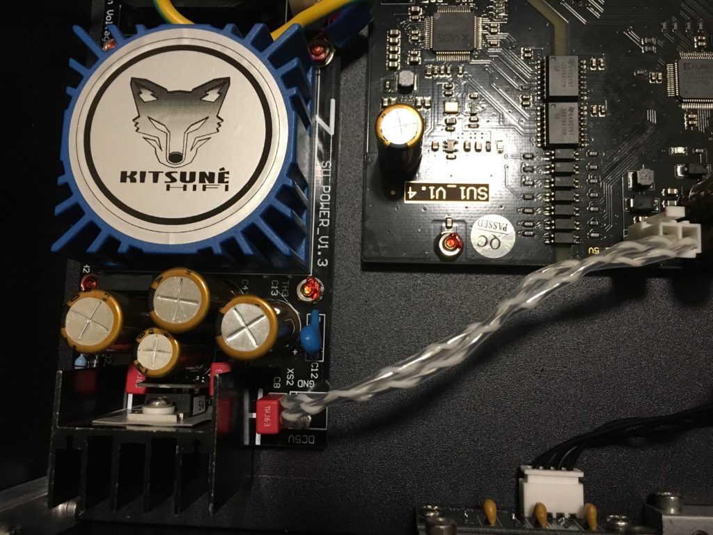 Pure silver OCC solid core wire was used for the PSU to mainboard connection (new film caps and power caps
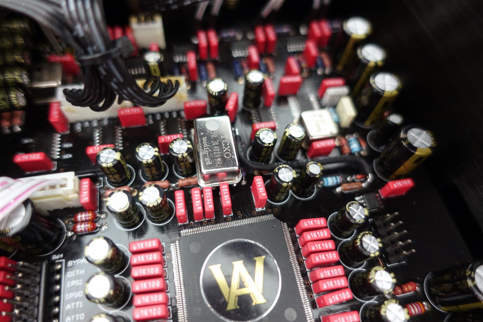
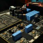
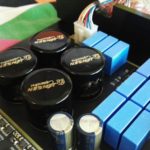
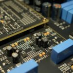
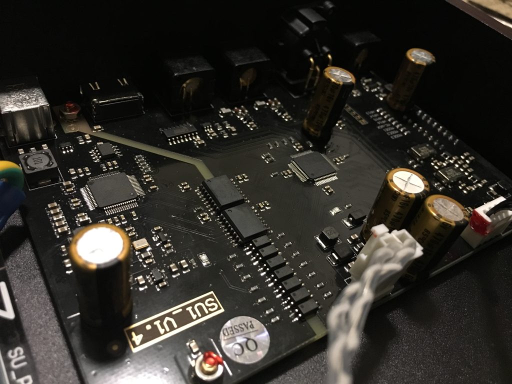 Take note the new 5 caps used on the mainboard
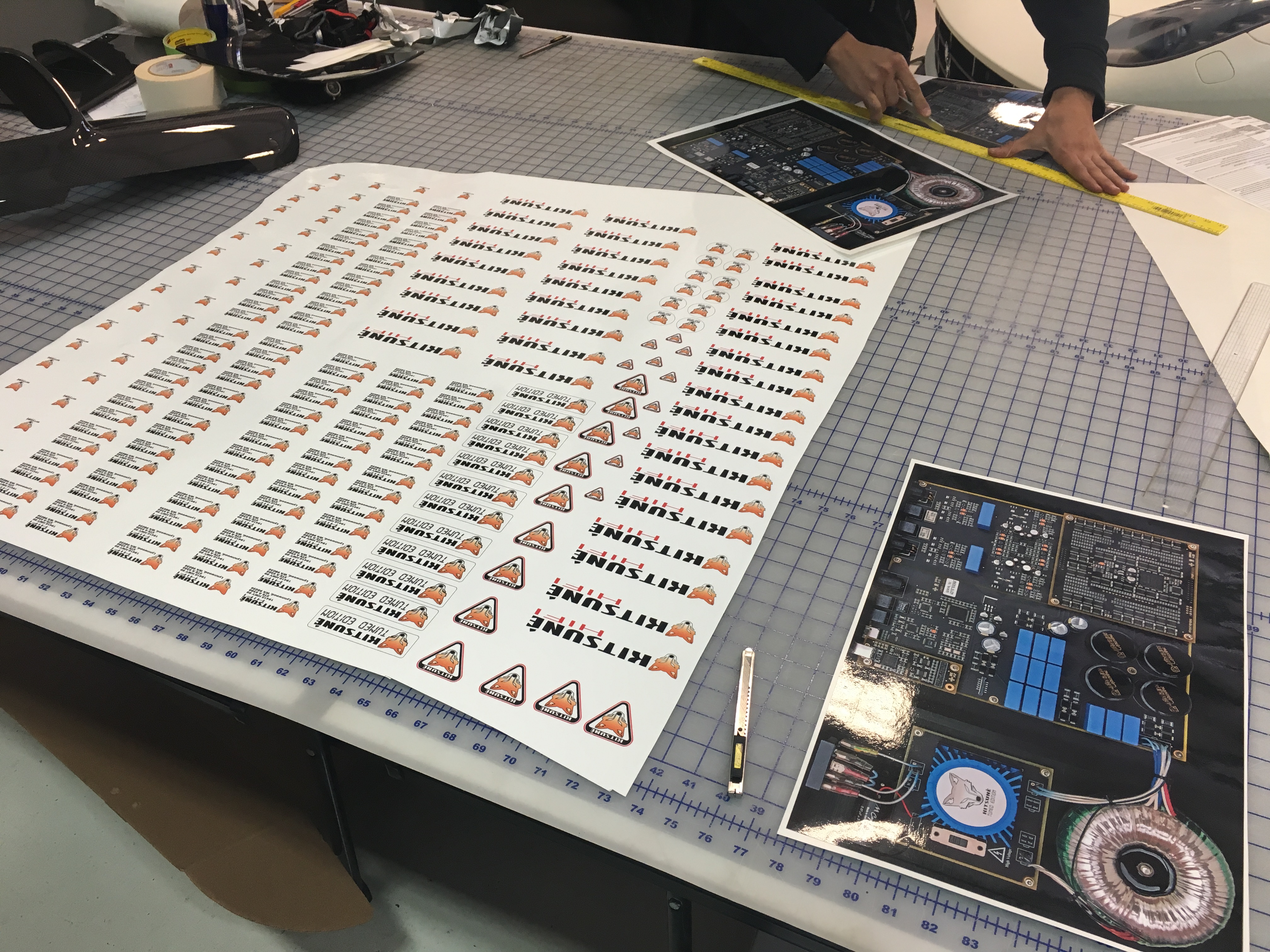
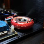
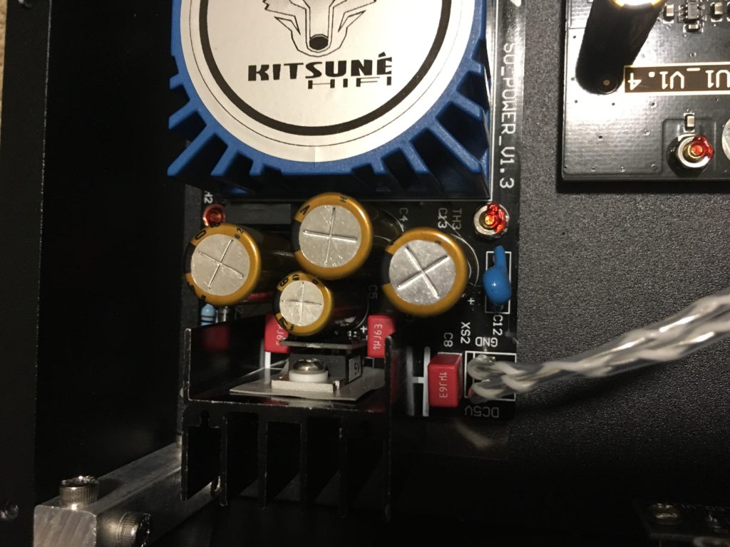 Excellent components have been chosen for the SU1 KTE. New photos will be updated soon to show current components in use. They are different than photos and improved design since these photos were taken.

